Flow Factor Line Card
Click to Contact Flow Factor
American Meter Gas Meters
Ametek Gauges
Ariston Mini-tank Water Heaters
Armstrong Pumps
ASCO Solenoid Valves
Barksdale Pressure and Temperature Switches
Barnes Pumps
BelGas Gas Regulators
Bosch Tankless Water Heaters
Carlo Gavazzi Level Switches
Chromalox Immersion Heaters
Co-Ax Valves
Carlon Water Meters
Elster Gas Meters
Fenwal Temperature Switches
Jefferson Solenoid Valves
MDI Float Level Switches
Parker Skinner Solenoid Valves
Parker Premier Aftermarket Water and Steam Valves
Penberthy Jet (eductors) Pumps
Penberthy Site Flows
Process Technology Immersion Heaters
See-Flo Flow Meters by ERDCO
Snap-Tite Valves
SSAC Conductive Level Systems
Watlow Immersion Heaters
To request a Quote please email us at info@flowfactor.com or call 866-360-9830
www.flowfactor.com
Flow Factor
Cleveland, Ohio USA
216-765-4231
Showing posts with label Armstrong. Show all posts
Showing posts with label Armstrong. Show all posts
Monday, June 22, 2015

Sunday, June 24, 2012
Armstrong H Series Bronze Pumps
H Series Circulators by Armstrong and Flow Factor

Armstrong Series S & H in-line circulators
are suitable for applications such as hydronics heating and cooling, domestic
water systems, multistage zoning and general industrial service. Both models
are available in a wide range of sizes to match the performance requirements of
any of these applications. Armstrong Series S & H circulators are durable
and trusted products that have been used by HVAC professionals for decades.
Design Features
Armstrong Series H in-line circulators
are built using a standard three-piece design that features a radially-split
body, oversized shaft, centrifugal impeller, positive mechanical seal and
modular construction.
The radially-split body can be left in line
while servicing the pump, eliminating cumbersome disconnecting of pipes.
Armstrong circulating pumps have oversized
shafts made from special alloy steel, machined to exacting tolerances.
Shafts have integral thrust collars,
heat-treated to provide long life under severe working conditions.
The balanced, centrifugal-design impeller
ensures maximum water delivery in the HVAC system.
A proven method of preventing water leakage,
the well known ARMseal construction is a frequently imitated feature of
the Armstrong circulator. Made from long lasting hard-wearing materials, it
ensures many years of noise-free, trouble-free service.
Models H-32 through H-54
feature a unique Armstrong shaft and bearing module which fi ts all of these
models for ease of serviceability and reduced inventory costs.
Note GPM (Gallons Per Minute) flow rates are determined by head pressures and restrictions. The max flow rate is with no head pressure and no restrictions.
H-51 1/4 HP 208/230/460 3 Phase Lead Free Pump
H-52 1/3 HP 115 VAC 0-48 gpm Lead Free Pump
H-52 1/3 HP 208/230/460 3 Phase Lead Free Pump
| 116444LF-137 |
| 116456LF-137 |
H-66 3/4 HP 208/230/460/575 3 Phase Lead Free Pump
Go To All Armstrong Pumps on Flow Factor
Contact Flow Factor with our form submittal or call:
866-360-9830
Armstrong ASTRO 2 Wet Rotor Pumps
The Armstrong ASTRO series circulators has been improved with the NEW ASTRO 2 series. Please note that the new series pumps do not retro fit with the old series and have different dimensions.
You can view the ASTRO 2 pdf file here.


You can view the ASTRO 2 pdf file here.
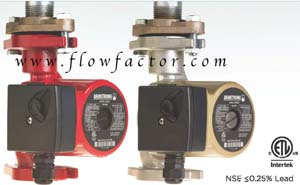
Armstrong Astro 2 3-speed circulators provide unmatched
performance over a wide range of head and flow requirements. The 3-speed design
allows users to match the requirements of an installation exactly, and also
helps with:
Reduced Inventory – the
complete range of 10 Astro 2 3-speed circulators replaces 93 models of
competitors’ pumps
Adaptability – After a
circulator is installed you might need to change the performance to
accommodate:
Over/under estimated system resistance in the original design.
Increased number of zones due to a building addition.
Addition of system elements such as an indirect hot water tank
or spa.
With
Astro 2 3-speed units installed you can easily change the operating speed to
handle these changed performance requirements.
Other
features of the Armstrong ASTRO 2 circulation pumps:
Compliance with lead-free regulations
Lead-free
bronze and stainless steel models of Astro 2 certified <0.25 weighted
average percent lead and complies with California Health and Safety Code
Section 116875 (commonly known as AB1953).
International code compliance
Astro
2 units are ETL listed for the US and Canada and conform to UL std. 778 and
Canadian electrical safety standards CSA std C22.2 No 108-01.
3-speeds
Reduce your inventory with a
variety of performance curves. Ten pumps replace 93 circulators. Correct design
issues in the field by adjusting the circulator output.
The Armstorng ASTRO Express Hot water Delivery System provides instant hot water at the tap where the Express valve is located. The system includes an Astro 220 SSU w/timer & 6 ft. Line cord, union hardware kit, Astro Express LF Valve.
Featured pumps for in home recirculation. Pumps with the TA suffix come with the timer and Aquastat. Great for hot water recirculation.
Armstrong Astro2 220BU Union Circulator, Stainless Steel, 0-6 GPM to 4 Ft. Head
Armstrong Astro2 225BS-3/4 Sweat Circulator, Bronze LeadFree, 0-11 GPM to 9 Ft. Head
Armstrong Astro2 230B Flange Circulator, Stainless Steel (P/N 110223-006), 0-13 GPM to 15 Ft. Head
Armstrong Astro2 250B Flange Circulator, Stainless Steel, 0-15.5 GPM to 22 Ft. Head
Armstrong Astro 2 250SS-TA Circulator Pump, Stainless Stl. w/Timer/Aquastat,0-15.5 GPM to 22 Ft. Head
Armstrong Astro 2 230SS-TA Circulator Pump, Stainless Stl. w/Timer/Aquastat, 0-13 GPM to 15 Ft. Head
Flow Factor also has Armstrong Union and Flange sets for all their pumps.
Please view the complete Armstrong ASTRO 2 listing here.
Call Flow Factor @ 216-765-4231
email at info@flowfactor.com
Armstrong S Series Cast Iron Circulators
Armstrong Series S CAST IRON Pumps From Flow Factor


Armstrong S Series circulators feature the unique Armstrong shaft and bearing module for ease of serviceability and maximum interchangeability. Oversized shafts of alloy steel machined to exact tolerances. Impellers are constructed from non-ferrous material and are designed for optimal water delivery. Available in bronze-fitted and all-bronze construction. CAST IRON CICULATORS ARE USED WITH BOILERS AND OTHER NONPOTABLE circulation applications.
Design Features
- Standard Three-Piece Design
- Radially-Split Body
- Oversized Shaft
- Centrifugal Impeller
- Positive Mechanical Seal
- Modular Construction
S-25 1/2 HP 115 VOLT 0-30 GPM 174031-013
S-35 1/6 HP 115 VOLT 0-75 GPM 174033-013
S-45 1/4 HP 115 VOLT 0-110 GPM 174036-113
S-46 1/3 HP 115 VOLT 0-115 GPM 174037-113
S-55 1/2 HP 115/230 VOLT 0-122 GPM 106284-132
S-55 1/2 HP 208-230/460/575 VOLT 3 phase 0-122 GPM 106284-136
S-57 3/4 HP 115/230 VOLT 0-140 GPM 106285-132
S-57 3/4 HP 208-230/460/575 VOLT 3 phase 0-140 GPM 106285-136
S-69 1 HP 115/230 VOLT 0-145 GPM 106531-132
S-69 1 HP 208-230/460/575 VOLTS 3 phase 0-145 GPM 116535-136
Armstrong Series S pumps can be used in HVAC, Hydronic, commercial and light industrial applications.
Please call Flow Factor at 866-360-9830.
www.flowfactor.com
S-55 1/2 HP 115/230 VOLT 0-122 GPM 106284-132
S-55 1/2 HP 208-230/460/575 VOLT 3 phase 0-122 GPM 106284-136
S-57 3/4 HP 115/230 VOLT 0-140 GPM 106285-132
S-57 3/4 HP 208-230/460/575 VOLT 3 phase 0-140 GPM 106285-136
S-69 1 HP 115/230 VOLT 0-145 GPM 106531-132
S-69 1 HP 208-230/460/575 VOLTS 3 phase 0-145 GPM 116535-136
Armstrong Series S pumps can be used in HVAC, Hydronic, commercial and light industrial applications.
Please call Flow Factor at 866-360-9830.
www.flowfactor.com
Saturday, June 9, 2012
Armstrong and Toshiba Pumping Systems
Pumps and Drives for Flow Control from Flow Factor.
Flow Factor sells circulating pumps by Armstrong
We carry a variety of Armstrong Astro Circulators, including Bronze
body pumps for potable water (domestic drinking), Iron body pumps for service
water (boilers), and Bronze body pumps with Timers and an Aquastat option for
hot water recirculation.
Armstrong Astro hot
water recirculation systems automatically circulate
water through domestic hot water distribution pipes. This helps to ensure that
everyone in the household has "instant" hot water at the tap when
they need it, while also helping to conserve water and save water heating
energy costs. Aquastat equipped models help save even more energy.
Also the Armstrong Light Commercial and Residential circulators, Series
S and H are available at Flow Factor. Both S series and H Series Armstrong circulators feature the unique Armstrong shaft and
bearing module for ease of serviceability and maximum interchangeability.
Oversized shafts of alloy steel machined to exact tolerances. Impellers are constructed
from non-ferrous material and are designed for optimal water delivery. The
Armstrong Series S and H are available in bronze-fitted and all-bronze
construction.
Coming Soon, the Armstrong PiB or Pump-in-a-Box to Flow Factor.
The
PiB series builds on the high quality and unsurpassed performance you've come
to expect from Armstrong. PiB (Pump-in-a-Box) models are packaged for warehouse
distribution and, for a large selection of sizes, guaranteed for delivery
within 72 hours of order. All other sizes are delivered seven working days from
order. Current PiB offerings include the Armstrong 4380 single head in line
range in fixed speed and Intelligent Variable Speed (IVS) Sensorless versions
and the Armstrong 4392 twin in line range in fixed speed and IVS Sensorless
versions. The offering covers an extensive range of predetermined impeller and
motor combinations, covering a wide range of head and flow requirements.
Call
for Quote.
Flow Factor Sells Adjustable Speed Drives by Toshiba for Pumps.
The Toshiba P9 Drive has been newly designed
exclusively for Pump Control. The Toshiba P9
adjustable speed drive is a revolution in pump control. By
incorporating Toshibafs proprietary, ground-breaking
Virtual Linear Pump (VLP) Technology, the P9 directly, precisely, and linearly
controls pressure, temperature or flow. The Toshiba P9 eliminates many
obstacles users thought were an integral part of pump control and sets a new
standard in ingenuity, performance, and ease-of-use for the pump industry.
The Toshiba P9 pump drives are available in 230 and
460 volts and from .75 HP to 400HP.
The P9 drives can come with Assembly boxes with
over load protection and bypass capabilities as well as dynamic braking, both
Standard and Heavy Duty.
Features of the Toshiba P9 are:
•
Linearizes Traditional Non-Linear Pump Curve,
Providing Userfs System with Stable &
Precise variable Pumping Control
•
Solves Problem of Load-Balancing Over Multiple
Pumps
•
Allows User to Configure System in Five Simple
Steps, VLP Provides User with Complete Control in only Minutes
•
Self-Calibrates & Eliminates Common Pump
Anomalies
•
Protects Against Cavitation & Provides Thrust
Bearing Protection
•
Maximizes Energy Savings on Variable Torque Loads
SPECIAL TOSHIBA P9 VLP FEATURES/PROTECTION
•
Proprietary VLP Technology; VLP Wizard
•
Booster Pump Control - Across the line or via ASD
•
Sensorless Operation
•
Automatic Sleep Function
•
Sealing Water Control Interlocks
•
No Flow/Low NPSH Cut-Off
•
Thrust Bearing Protection
Friday, March 23, 2012
NFPA 70 E Safety (Meltric) and OSHA
NFPA 70E: THE STANDARD FOR ELECTRICAL SAFETY IN THE WORKPLACE
As the foremost consensus standard for electrical safety in the workplace, NFPA 70E is the primary resource for employers to use in determining how to comply with OSHA’s electrical
safety regulations. It is also used by OSHA and the courts in the investigation of injuries in order to assess whether or not the involved employers took reasonable steps and precautions to protect their employees.
The key elements of the standard are summarized below. Complete details should be obtained from the standard itself. In Canada, CSA recently published CSA Z462 ‘Workplace Electrical Safety’ which is based on and is harmonized with NFPA 70E. Key elements in CSA Z462 are essentially the same as those found in NFPA 70E.
Article 110 – General Requirements for Electrical Safety-Related Work Practices
Training Requirements (110.6)
Employees who may be exposed to electrical hazards must be specifically trained to understand the
hazards associated with electrical energy as well as the safety-related work practices and procedures required to provide protection from them. The level of training provided determines the tasks that an employee is qualified to perform.
Only specially ‘Qualified Persons’ may perform work on or near exposed and energized electrical conductors or circuit parts. The training requirements include:
- How to recognize the potential hazards that exist
- How to distinguish energized from non-energized parts
- How to determine the voltage of exposed energized electrical conductors
- The relationship between the hazard and potential injury
- How to avoid exposure to the hazards
- How to select appropriate personal protective equipment
- Specific work practices and procedures to be followed
- Emergency procedures for assisting victims of electrical incidents
- How to perform a hazard/risk analysis
- How to determine approach and flash protection boundaries
Electrical Safety Program (110.7)
Employers are required to implement and document an electrical safety program to direct employee activities in a manner that is appropriate for the different voltage, energy level and circuit conditions that may be encountered. This safety program shall include all electrical safety procedures, be documented in writing, and be made available to all employees. If work on or near energized electrical conductors and circuit parts operating at 50V or more is required, the safety program must:
- Include a procedure that defines requirements and provides guidance for workers as they perform
work on or near live parts - Identify the hazard/risk evaluation procedure to be used before work is started within the limited approach boundary of energized electrical conductors and circuit parts operating at 50 volts or more.
- Include a job briefing process to inform employees of the hazards, proper procedures, special precautions, energy source controls and PPE requirements
Working While Exposed to Electrical Hazards (110.8)
Safety work practices consistent with the nature and extent of the associated electrical hazards shall be used to safeguard employees from injury while working on or near exposed electrical or circuit parts that are or can become energized. Two primary conditions are identified and addressed:
- Energized Electrical Conductors and Circuit Parts – Safe Work Condition. Live parts to
which an employee might be exposed shall be put into an electrically safe work condition before employees can work on or near them, unless work on energized components can be justified
according to section 130.1. - Energized Electrical Conductors and Circuit Parts – Unsafe Work Condition. Only qualified persons may work on electrical conductors or circuit parts that have not been put into an electrically safe work condition.
The requirements for establishing an electrically safe work condition are indicated in Article 120, while
the requirements for work involving electrical hazards are covered in Article 130.
Article 120 – Establishing an Electrically Safe Work Condition
The most effective way to prevent an electrical injury is to completely remove the source of electrical
energy and eliminate the possibility of its reappearance. To do so, workers must identify and disconnect
all possible sources of electricity.
Process of Achieving an Electrically Safe Work Condition (120.1)
- Identify all possible sources of electric supply.
Care should be taken to identify the possible presence of secondary sources. - Properly interrupt the load current(s) and open the disconnecting device(s).
Not all disconnecting devices are rated to interrupt load currents; this should only be done with a properly rated device. - Verify deenergization through visual inspection of the disconnect contacts.
Disconnecting means may sometimes fail to open all phase conductors when the handle is operated,
so it is necessary to verify physical contact separation. If this requires removing the disconnect
door or cover, appropriate PPE must be used. - Apply lockout/tagout devices.
This should be done in accordance with a formally established company policy. - Use a voltage detector to test each conductor to which the worker may be exposed in
order to verify deenergization.
The voltage detecting device must be functionally tested both before and after taking the measurements in order to ensure that it is working satisfactorily. - Circuit parts with induced voltages or stored electrical energy must be grounded.
If the conductors being deenergized could contact other energized conductors or circuit parts, grounding devices rated for the available fault duty should be applied.
Justification (130.1)
Deciding to work on or near energized electrical conductors and circuit parts should be a last resort in
the workplace, after all other opportunities for establishing an electrically safe work condition have been exhausted. Work on energized parts at 50V or more should only be performed if the employer can demonstrate that deenergizing will introduce additional hazards or is not feasible due to equipment
design or operational limitations.
When non-routine work must be performed on energized parts, a detailed work permit must be
prepared before the work can start. The work permit must document the following elements and be approved by a responsible manager or safety officer:
- A description of the circuit and equipment to be worked on
- Justification for performing the work in an energized condition
- A description of the safe work practices to be employed
- Results of the shock hazard analysis
- Determination of shock protection boundaries
- Results of the flash hazard analysis
- The flash protection boundary
- The personnel protective equipment required for worker safety
- Restricted access of unqualified persons from the work area
- Evidence that the job briefing has been completed
Approach Boundaries to Energized Electrical Conductors or Circuit Parts (130.2)
Limited, restricted and prohibited approach boundaries must be determined in order to identify safe approach distances and the precautions required to minimize the possibility of shock.
Arc Flash Hazard Analysis (130.3)
An arc flash hazard analysis shall be done in order to protect personnel from the possibility of being injured by an arc flash. As part of this analysis, flash protection boundaries must be determined based on available bolted fault currents and the incident energy exposure level for personnel working within this boundary must be calculated.
Personal and Other Protective Equipment (130.7)
Employees working in areas where electrical hazards are present shall be provided with, and shall use, protective equipment that is designed and constructed for the specific part of the body to be protected
and for the work to be performed.
Requirements for eye, hand, head and body protection and/or v-rated tools are determined based on the hazard/risk category for the work to be performed. The standard provides a reference table indicating the hazard/risk category for many of the electrical tasks performed in industry and also provides a chart showing the protective equipment that is required for each hazard/risk category.
The tables below show the hazard/risk categories for several common tasks and describe the protective equipment required for each of the categories.
Panelboards or Switchboards Rated >240V and up to 600VCB or fused switch operation with covers on RISK level 0
CB or fused switch operation with covers off RISK level 1
Work on energized parts, including voltage testing RISK level 2*
Other 600V Class (277V through 600V, nominal) Equipment
Opening hinged covers (to expose bare, energized parts) RISK level 1
Removal of bolted covers (to expose bare, energized parts) RISK level 2*
| Typical Protective Clothing Systems |
|---|
Long sleeve shirt and pants plus safety glasses, hearing protection and gloves for RISK level 0
Arc-rated (level 4) long sleeve shirt, pants, coverall, face shield, jacket, leather gloves
and work shoes for RISK level 1
and work shoes for RISK level 1
| Arc-rated (level 8) long sleeve shirt, pants, coverall, face shield, jacket, leather gloves and work shoes for RISK level 2 |
and work shoes for RISK level 2*
Meltric Connectors for Pumps (NFPA70E)


meltric PUMP CONNECTORS
For Safety convenience, use Meltric
deContactors to connect your Armstrong
pumps to your power source. As disconnect switches they can be used up to 200 amps. The switches have Poly or metal housings.
Meltric has handles or angle brackets for connecting to a junction box. AND, if you are worried about NFPA70, stop worring:
NFPA 70E Workplace Electrical Safety Standards apply to MCC’s and switchgear and also to plugs & receptacles used to connect welders, pumps, and other portable equipment. Because many of the plugs and receptacles currently in service have accessible live parts and can be hazardous if connected or disconnected under load, users must either update their equipment or follow cumbersome safety procedures in order to comply with NFPA 70E. AND in the National Electric code, Sections 430.102 – 430.109 of the National Electric Code require approved disconnecting means to be located in a readily accessible location within sight of the motor and driven equipment. With their UL & CSA ratings for “Motor Circuit Disconnect Switching” and “Branch Circuit Disconnect Switching”, Decontactor devices are an approved ‘line of sight’ disconnect switch for meeting this requirement. MELTRIC fills the bill for compliance!! Decontactor plugs and receptacles are ideal for pump connections up to 60 hp or 200 amps. Using Decontactors to connect power to pumps instead of hard-wiring can reduce downtime related to pump servicing by 50% or more. A qualified technician can safely disconnect power to the pump simply by removing the Decontactor plug which can then be easily locked out to ensure safety. The technician can then service the pump in complete safety. When service work is complete the technician can reconnect power simply by plugging the Decontactor plug back into the receptacle.
- No waiting for an electrician to perform field wiring
- No “suiting-up” or extraordinary electrical precautions
- Overload testing includes 50 opening and closing operations performed at 600% of full load motor ampacity with a power factor of 0.5 or less.
- All hp-rated Decontactor devices are rated to close into and withstand short circuit currents up to 100kA in circuits protected with RK1 fusing.
Note: Although Decontactor plugs and receptacles are rated to safely make and break motor loads, they are not rated or intended for continuous use as a motor starter.
Sections 430.102 – 430.109 of the National Electric Code require approved disconnecting means to be located in a readily accessible location within sight of the motor and driven equipment. With their UL & CSA ratings for “Motor Circuit Disconnect Switching” and “Branch Circuit Disconnect Switching”, Decontactor devices are an approved ‘line of sight’ disconnect switch for meeting this requirement.Decontactor plugs and receptacles are available with numerous handles, mounting angles, wall boxes, and other accessories. They may be used as in-line connectors or may be mounted on walls, panels, equipment, or even directly on the motor. This flexibility makes it simple to locate disconnects where they are easily visible and convenient to use.
Meltric DSN Series
- 20A to 60A
- Max 20hp
- NEMA 4X
- Low Cost, Compact
Compact, lightweight design
Automatic NEMA 4X watertightness
Most industrial applications
Wet or washdown environments
Plug & play electrical connections
UL 1682, UL Subject 2682,
CSA C22.2 No. 182.1
IEC 60309-1, 60947-3, AC22, AC23
FEATURES:
Switch Rates
safety shutter/dead front
spring loaded butt contacts
silver-nickel contacts
lockout-tagout capabilty
watertight
quick break mechanism
enclosed arc chambers
spring-assisted terminals
NEMA 4X, IP66+IP67
Subscribe to:
Posts (Atom)